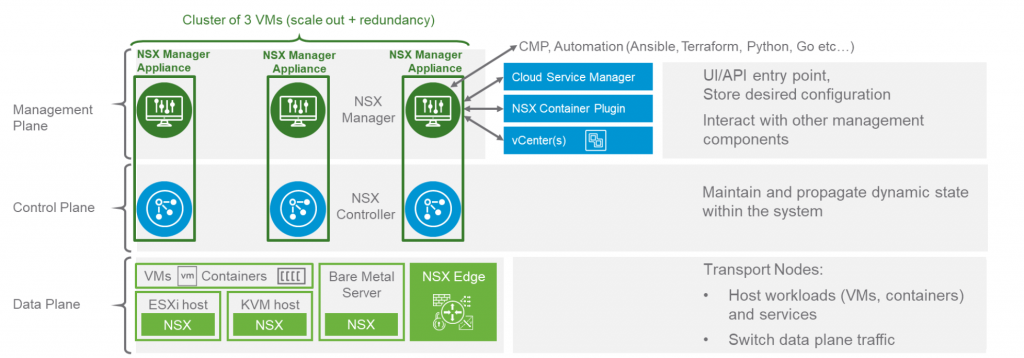
After a quick overview of NSX-T Architecture and Components we will take a deeper look into how logical switching is done in NSX-T.
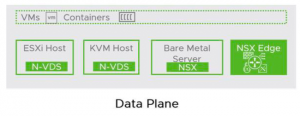
N-VDS
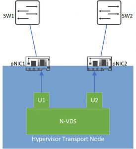
The main component of NSX-T Logical Switching is the NSX Virtual Distributed Switch or N-VDS. An N-VDS is created on every Transport Node* (TN) when it is prepared for NSX. N-VDS on ESXi hypervisors is based on VDS and on KVM hypervisors it is based on OVS. Like any other switch, an N-VDS has downlink or server ports which connects VM and also Uplink ports to connect the N-VDS to Physical Network Interface Cards (pNIC). Note that N-VDS Uplinks are not the same as pNICs of a host, but these uplinks are assigned to pNICs so that the N-VDS can communicate with the outside world (other hosts, etc.)
Different types of virtual switches (VSS, VDS, N-VDS) can co-exist on a single host but a pNIC can be assigned to only one virtual switch. We can also bundle pNICs of a host and form a LAG (Link Aggregation Group) and assign N-VDS Uplinks to a LAG instead of a single interface.
* With the exception of BareMetal servers.
Teaming Policy
The teaming policy defines an N-VDS’s uplink failover and redundancy mechanism as well as how the traffic is balanced between the uplinks. Following teaming policies are available for N-VDS Uplinks
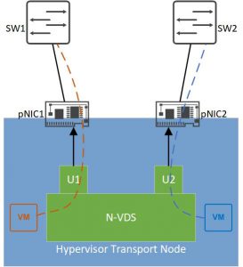
- Failover Order (ESXi, KVM): in this mode, one uplink is active and other ones are in standby mode. If the active uplink fails the next standby uplink will become active and forward the traffic. We can define one uplink as active and put several uplinks in a standby list.
Failover Order
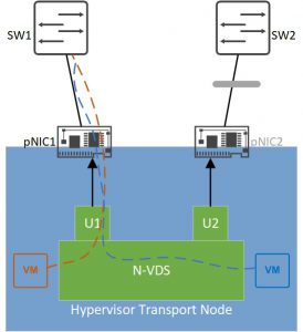
- Load Balance Source (ESXi only): in this mode, a 1:1 mapping is made between the virtual interface of a VM and an uplink port. Traffic sent from that VM interface will always leave the N-VDS via the mapped uplink.
Load Balance Source
- Load Balance Source MAC (ESXi only): in this mode, the mapping is not done between a VM interface and an uplink but between a VM MAC address and an uplink, so if a VM has more that one MAC address, each MAC address can use a separate uplink to send traffic.
Note that the teaming policy has nothing to do with the redundancy and load balancing on pNICs in a LAG. For instance, if we use Failover Order teaming policy for the Uplinks of an N-VDS, we can still assign the active and standby uplinks to LAG interfaces. In this case the active Uplink interface fails when all interfaces in the LAG are down. We are also totally free to assign one Uplink interface to a LAG and another one to a single pNIC.
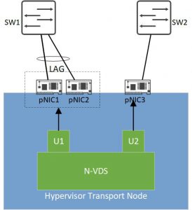
LAG and Single pNIC combination
Named Teaming Policy
Teaming Policies we’ve discussed so far are default policies, on ESXi hypervisors we can overrule the default teaming policy by a so called “named policy”. With a named policy we can steer a specific traffic type (management for instance), in a different way than the default traffic flows. For instance, we configure a failover order as our default teaming policy and specify U1 as the active uplink. We can then define a named policy for our management traffic and specify U2 as the active uplink interface for this type of traffic.
- named policies are only supported in ESXi hypervisors.
- named policies can only apply to VLAN backed segments (read more about segments) .
Uplink Profiles
Uplink Profile is a way to ensure consistency of N-VDS uplink configuration. We create an uplink profile (template) and define the following parameters in it and the apply it to uplink ports of N-VDS switches in different hosts.
- The format of the uplinks of an N-VDS
- The default teaming policy applied to those uplinks
- The transport VLAN used for overlay traffic*
- The MTU of the uplinks
- The Network IO Control profile (read ore about NIOC)
* a transport VLAN is the VLAN which carries the overlay (encapsulated) traffic of an N-VDS in the physical network.
Latest Reactions